![]()
NOTE: At this time, bitmaps are only supported in CADFusion projects that target the A3200 motion control system.
Each bitmap starts with a source image that is converted to grayscale and all transparency is removed. You must specify the size of each pixel that is marked by the tool that is attached to your system. If you use a laser to mark the bitmap, the marking pixel size is typically the spot size of the laser.
CADFusion uses the marking pixel size and the size that you make the bitmap on the canvas to subdivide each pixel into a square grid of marking pixels. Each square of marking pixels has the same grayscale value as the original image pixel that it contains. Refer to the figure that follows.
The table that follows describes the Marking Modes that you can use for marking a bitmap.
Table: Marking Modes
In the Marking Settings area of the Add Tools or Edit Tools dialog you must select a Marking Mode. If you select one of the Monochrome marking modes, each marking pixel is converted from grayscale to black or to white. The conversion uses a threshold or it uses a process of dithering. Refer to the figure that follows.
| Original Image | Dithered (Floyd-Steinberg) |

|

|
| Threshold 134 | Threshold 88 |

|

|
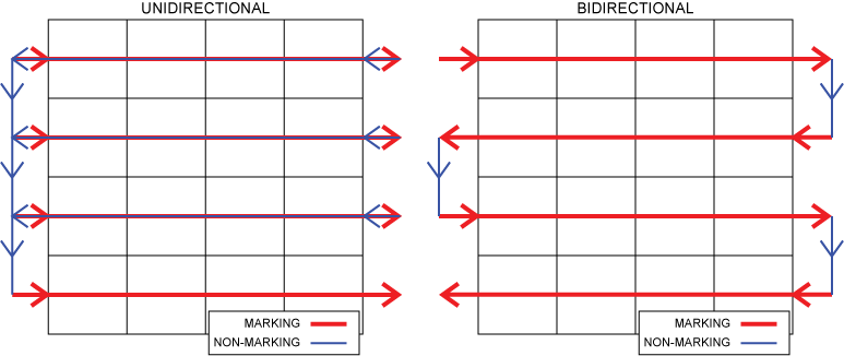
Marking starts at the top left corner of the bitmap image. You can configure the properties of the bitmap shape so that it the marking process uses Horizontal scans or Vertical scans. Also, you can specify the pattern in which the bitmap is marked. If you select Unidirectional, then all the marking scans occur in the same direction. If you select Bidirectional, the result is a serpentine motion.
If you use a laser and you select Bidirectional marking, the latency of the laser can cause the forward and reverse marking scans to look misaligned when you look at the result on your material. Typically, the results get worse as the marking speed increases. To align the forward and reverse marking scans, specify a Bidirectional Offset. The value that you specify is a positive distance in the units that you selected for your project. The Bidirectional Offset and the Overscan Distance values are added to the end of each forward marking scan. This causes each reverse marking scan to trigger the laser sooner to compensate for the delay caused by the laser latency. To find the best Bidirectional Offset for your system, experiment with different values until you find a value that has visually satisfactory results.
If you want to coordinate marking with motion on other axes or with the function of other process elements, use the Marking Initialization and Marking Termination settings on the Bitmap tool. For example, you can use these settings to start and stop a rotational axis that must move during marking scans, but that stops moving when marking is completed.
If the quantity of data that is necessary to mark the bitmap is more than the quantity that the drive can store, CADFusion pauses marking to download more data. If this occurs, marking pauses at the end of one or more marking scans to do another download. When the marking pauses, the Marking Termination code executes. After the download is completed and before marking starts again, the Marking Initialization code executes.